Difference between revisions of "Electromagnetic induction"
| Line 184: | Line 184: | ||
===Activities=== | ===Activities=== | ||
| − | ==Concept #3 - == | + | ==Concept #3 FLEMING'S LEFT HAND RULE AND WORKING OF MOTOR - == |
===Learning objectives=== | ===Learning objectives=== | ||
| + | #State Fleming's left hand rule of motor | ||
| + | #Explain working of motor | ||
| + | #Distiguish between dynamo and motor | ||
| + | #Application of the motor | ||
===Notes for teachers=== | ===Notes for teachers=== | ||
| + | Difference between A.C. and D.C | ||
| + | Direct current (D.C.) Alternating current (A.C.) | ||
| + | 1. It is the current of constant magnitude. | ||
| + | 2. It flows in one direction in the circuit. | ||
| + | 3. It is obtained from a cell (or battery) | ||
| + | 1. It is the current of magnitude varying with time. | ||
| + | 2. It reverses its direction periodically while flowing in a circuit. | ||
| + | 3. It is obtained from A.C. generator and mains. | ||
| + | |||
| + | Advantages of A.C. over D.C.: | ||
| + | In India, we use 220 volt a.c. in our houses and factories. The use of A.C. is advantageous over D.C. because the voltage of A.C. can be stepped up by the use of a step-up transformer at the power generating station before transmitting it over the long distances. It reduces the loss of electric energy as heat in the transmission line wires. The A.C. is then stepped down to 220 volt by the use of step-down transformers at the successive sub-stations before supplying it to the houses or factories. If D.C. is generated at the power generating station, its voltage cannot be increased for transmission and so due to passage of high current in the transmission line wires; there will be a huge loses of electrical energy as heat in the line wires. | ||
| + | |||
| + | A.C. Generator D.C. Motor | ||
| + | 1. A generator is a device which converts mechanical energy into electrical energy. | ||
| + | 2. A generator works on the principle of electrro magnetic inductions. | ||
| + | 3. In a generator, the coil is rotated in a magnetic field so as to produce electric current. | ||
| + | 4. A generator makes use of two separate coaxial slip rings. | ||
| + | 1. A d.c. motor is a device which converts electrical energy into mechanical energy. | ||
| + | 2 d.c. motor works on the principle of force acting on a current carrying conductor placed in a magnetic field. | ||
| + | 3. In d.c. motor, the current from d.c. source flows in the coil placed in a magnetic field due to which the coil rotates. | ||
| + | 4. A d.c. motor makes use of two parts of slip ring (i.e., split rings) which act as a commutatar. | ||
| + | |||
===Activities=== | ===Activities=== | ||
| − | #Activity 1 - | + | #Activity 1 - |
==Concept #4 == | ==Concept #4 == | ||
Revision as of 16:16, 24 August 2014
Concept Map
Error: Mind Map file Electromagnetic induction.mm not found
Textbook
- Tenth Standart Science Textbook
Additional information
Useful websites
- http://en.wikipedia.org/wiki/Electromagnetic_induction
- http://www.youtube.com/watch?v=vwIdZjjd8fo
- http://www.electronics-tutorials.ws/electromagnetism/electromagnetic-induction.html
- https://www.google.co.in/search?q=electromagnetic+induction&oq=Ele&aqs=chrome.0.69i59l2j69i57j0l3.1895j0j8&sourceid=chrome&es_sm=93&ie=UTF-8
Reference Books
- Tenth Standard Ready Lesson CD from Education Department – Science Subject
Teaching Outlines
Concept #1 Electro magnetic Induction
Learning objectives
- Recall the the properties of magnets
- Electromagnetic effect
- How emf induced
- Emf depends upon the number of turns and speed of the magnet
- Michel Faraday experiment
Notes for teachers
Electromagnetic Induction
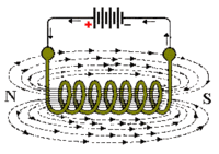
The magnetic flux developed around the coil being proportional to the amount of current flowing in the coils windings as shown.


If additional layers of wire are wound upon the same coil with the same current flowing through them, the static magnetic field strength would be increased.
Therefore, the Magnetic Field Strength of a coil is determined by the ampere turns of the coil. With more turns of wire within the coil the greater will be the strength of the static magnetic field around it.
But what if we reversed this idea by disconnecting the electrical current from the coil and instead of a hollow core we placed a bar magnet inside the core of the coil of wire. By moving this bar magnet “in” and “out” of the coil a current would be induced into the coil by the physical movement of the magnetic flux inside it.
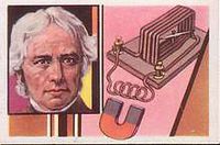
Electromagnetic Induction was first discovered way back in the 1830’s by Michael Faraday. Faraday noticed that when he moved a permanent magnet in and out of a coil or a single loop of wire it induced an ElectroMotive Force or emf, in other words a Voltage, and therefore a current was produced.
Faraday’s Law of Induction
- Increasing the number of turns of wire in the coil – By increasing the amount of individual conductors cutting through the magnetic field, the amount of induced emf produced will be the sum of all the individual loops of the coil, so if there are 20 turns in the coil there will be 20 times more induced emf than in one piece of wire.
- Increasing the speed of the relative motion between the coil and the magnet – If the same coil of wire passed through the same magnetic field but its speed or velocity is increased, the wire will cut the lines of flux at a faster rate so more induced emf would be produced.
- Increasing the strength of the magnetic field – If the same coil of wire is moved at the same speed through a stronger magnetic field, there will be more emf produced because there are more lines of force to cut.
Factors affecting the magnitude of induced emf: The magnitude of induced emf is equal to the rate of change of magnetic flux i.e., Induced emf= (Change in magetic flux)/(Time in which the magentic flux changes) i) the change in the magnetic flux and ii) the time in which the magnetic flux changes.
These are short notes that the teacher wants to share about the concept, any locally relevant information, specific instructions on what kind of methodology used and common misconceptions/mistakes.
Activity No # 1- Properties of Magnets
- Estimated Time
20 minute
- Materials/ Resources needed
- Magnets
- Magnetic needles with stand
- Prerequisites/Instructions, if any
- Multimedia resources
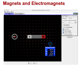
Goto Magnet & electromagnets simulations

- Website interactives/ links/ simulations
- Process (How to do the activity)
Give the magnets to students and check the properties of magnets. Ask the students properties of magnets. Give the inst
Ask magnetic lines of force using phet tool of magnets and electromagnet.
Give two magnets and a magnetic needle to students group (4-5students). Tell check the properties of magnets
- Developmental Questions (What discussion questions)
- Evaluation (Questions for assessment of the child)
1.If a magnetic needle placed along the north and south pole of a bar magnet as shown in the figure, what is the polarity of the a b c and d. mark 2
![]()
- Pole of a ________ *pole of b _______
- Pole of c _________ *Pole of d _________
- Question Corner
To link back to the topic page
Goto SCIENCE TOPIC page
Activity No # 2- Electromagnet Experiment
- Estimated Time
- Materials/ Resources needed
- A strong bar magnet
- Copper coil with 500 turns
- Galvanometer
- Prerequisites/Instructions, if any
- Multimedia resources
- Website interactives/ links/ simulations
- Process (How to do the activity)
Show the connection of copper coil and galvanometer.
- Developmental Questions (What discussion questions)
- Evaluation (Questions for assessment of the child)
- Question Corner
Activity No # 3- Electromagnetic Induction using Galvanometer
- Estimated Time
- Materials/ Resources needed
- Prerequisites/Instructions, if any
- Multimedia resources
- Website interactives/ links/ simulations
- Process (How to do the activity)
Show the electromagnetic induction using galvanometer and copper coil. Observe the changes of galvanometer deflections.
- Developmental Questions (What discussion questions)
- Evaluation (Questions for assessment of the child)
1.The device that detects the induced emf is called _________________ mark 1
2.Which the following emf is produced? Yes/no
a) Coil is steady, magnet is moved inside the coil _______________
b) Coil and magnet are moved away in opposite direction _______________
c) Magnet is steady, Coil is moved towards magnet ____________
d) Coil and magnet both are moved together __________________ mark 2
3.copper coil is connected to Galvanometer and a bar magnet. What are the changes in the following
- Magnet kept inside the coil ____________________________
- Magnet is pushed slowly ________________________________
- Magnet is pushed inside the coil very quickly _____________________ mark 2
- Question Corner
Activity No # 4- Factors influences emf
- Estimated Time
- Materials/ Resources needed
- Prerequisites/Instructions, if any
- Multimedia resources
- Website interactives/ links/ simulations
http://www.youtube.com/watch?v=vwIdZjjd8fo
- Process (How to do the activity)
Show the short video of number of coils increasing emf is increasing.
- Developmental Questions (What discussion questions)
- Evaluation (Questions for assessment of the child)
1. Which the following coil is more emf produced when magnet movement inside the coil? mark 1

2. A copper coil, a strong bar magnet and a led bulb are on the table. How do you glow on the led bulb? Mark 2
- Question Corner
Activity No # 5- Michel Faraday Experiment
- Estimated Time
- Materials/ Resources needed
- Prerequisites/Instructions, if any
- Multimedia resources
- Website interactives/ links/ simulations
- Process (How to do the activity)
Show the video of Michel Faraday experiment.
- Developmental Questions (What discussion questions)
- Evaluation (Questions for assessment of the child)
- Question Corner
To link back to the topic page Give the link of the page name from where activity was given Back
Concept #2 FLEMINGS RIGHT HAND RULE AND WORKING OF DYNAMO
Learning objectives
- State Fleming's Right hand rule of dynamo
- Know the main parts of dynamo
- Explain the working of AC dynamo
- Distriguish between AC dynamo and DC dyname
- Application of dynamo
Notes for teachers
Activities
Concept #3 FLEMING'S LEFT HAND RULE AND WORKING OF MOTOR -
Learning objectives
- State Fleming's left hand rule of motor
- Explain working of motor
- Distiguish between dynamo and motor
- Application of the motor
Notes for teachers
Difference between A.C. and D.C Direct current (D.C.) Alternating current (A.C.) 1. It is the current of constant magnitude. 2. It flows in one direction in the circuit. 3. It is obtained from a cell (or battery) 1. It is the current of magnitude varying with time. 2. It reverses its direction periodically while flowing in a circuit. 3. It is obtained from A.C. generator and mains.
Advantages of A.C. over D.C.: In India, we use 220 volt a.c. in our houses and factories. The use of A.C. is advantageous over D.C. because the voltage of A.C. can be stepped up by the use of a step-up transformer at the power generating station before transmitting it over the long distances. It reduces the loss of electric energy as heat in the transmission line wires. The A.C. is then stepped down to 220 volt by the use of step-down transformers at the successive sub-stations before supplying it to the houses or factories. If D.C. is generated at the power generating station, its voltage cannot be increased for transmission and so due to passage of high current in the transmission line wires; there will be a huge loses of electrical energy as heat in the line wires.
A.C. Generator D.C. Motor 1. A generator is a device which converts mechanical energy into electrical energy. 2. A generator works on the principle of electrro magnetic inductions. 3. In a generator, the coil is rotated in a magnetic field so as to produce electric current. 4. A generator makes use of two separate coaxial slip rings. 1. A d.c. motor is a device which converts electrical energy into mechanical energy. 2 d.c. motor works on the principle of force acting on a current carrying conductor placed in a magnetic field. 3. In d.c. motor, the current from d.c. source flows in the coil placed in a magnetic field due to which the coil rotates. 4. A d.c. motor makes use of two parts of slip ring (i.e., split rings) which act as a commutatar.
Activities
- Activity 1 -